MIL-DTL-22442/27C(AS)
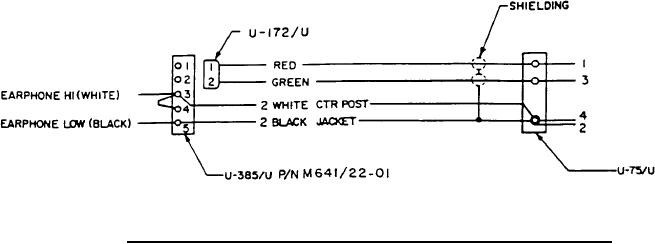
FIGURE 2. Cable assembly P/N M22442/27-l CX-13127/A Schematic Diagram.
APPLICABLE DOCUMENTS:
MIL-J-64l/22
-
Jacks, Telephone, U-385/U
REQUIREMENTS:
l. The cable cord shall be in accordance with M22442/35-l. The electrostatic and
electromagnetic isolation requirements of M22442/35-l are not required.
2. The weight of the cable assembly shall not be greater than 5 ounces.
3. The stay cord shall be firmly attached to the connectors.
4. The DC resistance shall be less than 2 ohms between the following contacts:
(a) Contact l of P/N M22442/5-l (U-75/U) and contact l of U-l72/U.
(b) Contact 3 of P/N M22442/5-l (U-75/U) and contact 2 of U-l72/U.
(c) Contact 4 of P/N M22442/5-l (U-75/U) and contact 3 of P/N M64l/22-0l (U-
385/U).
(d) Contact 2 of P/N M22442/5-l (U-75/U) and contact 5 of P/N M64l/22-0l (U-
385/U).
5. The "X" dimension shall be 42.25 +3 -.5 before coiling.
6. The cable assembly shall be tested in accordance with the tests listed in Table I.
NOTES:
l. All dimensions are in inches.
2. Tolerances are metal parts ±.005, molded sections ±.05 inches unless otherwise
specified.
2