MIL-DTL-22442/19D(AS)
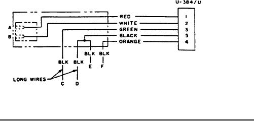
FIGURE 2. Cable assembly P/N M22442/l9-1, CX-12972/AR Schematic Diagram.
APPLICABLE DOCUMENTS:
MIL-J-641
-
Jack, Telephone General Specification for
MIL-P-642/l4 -
Plugs, Telephone (Type U-384/U) 5 Conductor, Single
MIL-C-10392 -
Cord, Electrical (Audio Miniature)
REQUIREMENTS:
*1. The cable (cord) shall be in accordance with MIL-C-10392 Type WM-59A/U or
equal.
2. The weight of the cable assembly shall not be greater than 3 ounces.
3. The stay cord shall be firmly attached to the connectors.
4. Single conductors shall have a nominal cross sectional area of 404 circular mils (No. 24
AWG) and shall be in accordance with specification MIL-C-10392 except that the outer
separator and jacket shall be omitted.
5. The single conductor connector shall be made of half-hard brass or equivalent finished
(as approved by the qualifying activity) with white nickel plate to 0.0004 inch minimum
depth. The finished dimensions shall be as shown in Figure l.
*6. The terminal block shall have dimensions and details shown in Figures l and 2 and
shall have provision for mounting on a pilot's helmet. The pins only, from jack JJ-048,
shall be molded in the terminal block and shall be in accordance with MIL-J-641 (see
3.4.4) .
7. The DC resistance shall be as indicated when tested with an ohmmeter.
(a). Terminal "A" and contact l of P/N M642/l4-0l (U-384/U) less than 2 ohms.
2