MIL-DTL-22442/22C(AS)
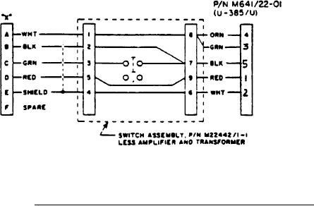
FIGURE 4. Cable assembly P/N M22442/22-2 Schematic Diagram.
APPLICABLE DOCUMENTS:
MIL-C-10392 -
Cord, Electrical (Audio, Miniature)
MIL-J-64l/22 -
Jacks, Telephone, U-385/U
MS3116
-
Connector, Plug, Electric, Series 1, Solder Type, Straight, Bayonet
Coupling
REQUIREMENTS:
l. The cable between the switch assembly and the "X" connector shall be in accordance
with MIL-DTL-22442/3. The cable between the switch assembly and the P/N M641/22-0l
(U-385/U) connector shall be in accordance with MIL-C-10392.
2. The weight of the cable assembly shall not be greater than 20 ounces.
3. The stay cord shall be firmly attached to the connectors and the switch assembly.
4. The amplifier shall be in accordance with M22442/l-2.
5. The transformer shall be in accordance with M22442/l-3.
6. Connector "X" shall be MS3ll6Fl0-6P or functional equivalent. Black tubing may be
used as a bushing under strain relief.
7. The DC resistance of the M22442/22-l cable assembly shall be as indicated when
tested with an ohmmeter.
(a) Contact A of "X" and contact B of "X" less than 100 ohms.
3